Wednesday 30 October 2019

7/4" Gauge Bagnall Contractors Locomotive

By the way of a change of pace, allow me to introduce another of my longer-term projects.
A  7 1/4" gauge Bagnall Saddle Tank locomotive.

Time away from teaching over the half-term break has allowed me to get in the workshop push this little project along a bit which feels good.


I am building this model more-or-less to a published design, known as Sweet William.  However I will be changing certain aspects of the model to speed-up the manufacturing process and hopefully create a more robust and easier to maintain and run model.  The tender which I have designed is totally out of scale but should provide a stable riding truck for the driver which should at least be in the spirit of the engine, and which I hope will look smart.


I've built the whole thing up in CAD, and I think it will be quite an attractive engine when finished.   The tender design incorporates a woefully out-of-scale coal rail, however I've added this to make the engine easier to push about when not in steam and provide something robust which I hope will not bend or break if manhandled.  My intention with this locomotive is that it should be a hard-working miniature machine rather than a exact scale model, and I think that details like this will improve it's longevity and hopefully prevent the paintwork becoming too knocked-about when subjected to out-of-scale abuse.


To speed up the build process, I've made extensive use of laser-cut pieces.   The image below shows the parts for the tender as I received them from the laser cutters.  


The parts simply slotted together and took less that 20 minutes to weld-up into a really strong construction.


The main frames are being assembled here and are of a mostly welded construction.


After a clean-up, time for a lick of paint.


The axleboxes on the published design have been replaced with self-aligning take-up bearings, more commonly used in conveyor belt mechanisms.  These should last a lifetime.


One of the tasks this week has been the pattern making for the cast iron cylinders.  Here, I'm testing the fit of the pattern whilst refining its design.  


The cab gets a quick coat of primer..


The drivers controls have started to go in.  That on the left is the reverser, and the screw handle on the right will apply the brakes.


And there she (it?) is.  I've enjoyed taking a break from the 1:56 models over the past week or so whilst on half-term, and getting stuck into working with some materials and processes where my experience and confidence is a little higher.

Just in case anyone is wondering whether I'd thought to make a miniature version of this already miniature locomotive, the answer is...Yes!  I have the parts drawn-up as a little laser kit, together with some rolling stock and I'll probably build one up once the Vickers Vernon is complete - although I do now have quite a backlog.  🙂


Until next time,  thanks for stopping by.

James

Sunday 27 October 2019

Schloss Itter : The Gatehouse design


Regular visitors to this blog and 28mm Victorian Warfare, will be familiar with the joint project between Michael Awdry and I to build in miniature a model of the Austrian castle at Itter, which played host to an unlikely, yet significant battle in the dying days of the Second World War.
Michael has been giving an excellent account of our progress, and in particular his magnificent efforts in bringing to life to the terrain pieces which I have been designing for the build.
As a reminder, I include the image below, which gives an overview of the model and the approximate terrain as the design stands to-date.


A significant element to the overall scene, and indeed the history of the battle, is the first of two gate houses which guard the approach to the castle from the village of Itter.


It is within this gatehouse that the 'Besotten Jenny', an American 'Easy Eight' Sherman tank was positioned as a first-line of defense for the unlikely allies who had taken-up defensive positions in the the castle itself.
Working from the photographs we had available it was a pleasurable task to recreate this iconic structure in miniature, although as always seems to be the case, I  overlooked one very important detail which is the source of some frustration for me.  More of that later.....
I like to begin projects like this by laying out the parts in 2d in the CAD software.  I really enjoy the process of building-up the parts in my head, considering the material they will be cut from, their thickness and how the parts will join together.


The image above shows how I tend to group similar parts into panels.  I like the creation of kits like this, and in this case each panel was sized to fit into an A4 envelope.  Should others like to recreate their own gatehouse at some point then at least the postage of the parts should be straightforward.
From this beginning, and quick mock-up was created to test the scale and fit of the elements.  Once again, Michael had to-hand the required hardware for the lash-up.


This mock-up presented a couple of minor issues, which whilst not visible in the photo above, did inspire me to think that I could do better.  So at this point I switched to the 3d CAD and refined the design.


Creating something like this in 3d takes quite a few hours to accomplish.  However, the action of building it up on screen first allows me to refine certain design elements which I hope will improve the final model.
For example, the gatehouse features some attractive stone corbelling above the main entrance.  Having studied this for some time, I wondered whether that might have something to do with the positioning of the roof structure.  Having decided that to be the case, I modified the structure to incorporate timber floor joists at that level, which led to the inclusion of the loft floor, from where Worsham and Mc Haley would have set-up their .30 caliber machine gun.
Unaware at the time quite how the upper floor was reached, and not wanting to design something which was obviously wrong I incorporated an access hatch through which our 'heroes' could pass.  I also designed a suitable ladder.  This hatch was tucked to one side of the structure, out of sight of any of the available photographs in the hope that no-one would be able to tell me it was wrong!
(I have since learned that the space was accessed via a spiral staircase in one of the towers which is a bit annoying!) 
I thought that the hatch may pose a health and safety risk, so included a small handrail to reduce the chance of an unfortunate accident.


With the final details decided upon, I set to building up revised model to test all was going to fit as anticipated.
Thin card was used to form the shape of the turret roofs, and laser-cut card roof tiles were applied to the main roof structure.


The turrets of the original were clad with timber shingles, so these were recreated too.


And so, content that my prototype parts would all fit as expected, a kit of parts was passed to Michael for him to work his magic.
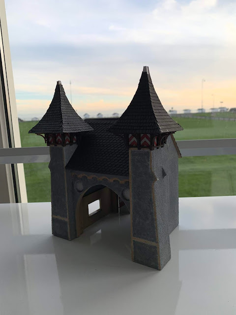
However, I had become quite taken by this little building so I determined to complete my own example and with some hesitation, I share my result thus far below.


I hope this little insight into my contribution towards the Schloss Itter project has been of interest, and I thank you for stopping by.

Finally, what of the important detail which I had mentioned earlier?, which I have got wrong...

Well, photographs of the gatehouse all tended to have been taken from a similar direction, from which it was difficult to determine what lay to the right-hand-side of the smaller doors to the rear of the gatehouse.  

It wasn't until after the model had been built that I thought to scour the internet for some additional images in the form of postcards of the castle.  This led me to a lovely postcard of the castle in winter.


This had been the first time I'd seen the gatehouse from this angle.  Imagine my horror when I zoomed in and found....


'Clear as anything, there was an extra door!!!!

I'm not sure whether I've told Michael about this discovery yet or not.  And I'm not too sure quite what I'm going to do about it.  However, as I said in my last post "If it's not right, it's wrong", and I fear there may have to be a gatehouse Mk 4.  If there is, then it will incorporate the spiral staircase too.

Should you be visiting Salute 2020, and the extra door is missing, please don't mention it!! 🙏


Until next time (and I hope it works!), I've added a little video fly-by of the CAD model.  I filmed it with my phone, so if it does work the quality might be questionable!

Best wishes,

James


Friday 18 October 2019

Vickers Vernon Part 4 - "If it's not right, it's wrong!"

This latest post will sadly show less progress with the Vernon, than I would have liked.  Not that I've been idle you understand, in fact I've been very busy.  However, on more than one occasion over the past few days I've discovered little annoyances with various projects which have left me to conclude; "If it's not right, it's wrong!".  And upon discovering something which isn't as good as I can make it be, then I just have to begin again.  All to often, the inner perfectionist in me has abandoned a project for the sake of a detail which once seen, I cannot un-see.
Therefore, whilst the progress on the model may be slight, the learning curve has been projecting upwards, and the light at the end of the tunnel is becoming ever more welcoming!  And, rather than give-up, I've faced my demons and pushed through which feels good.  This photograph shows some of the failures, I think there may be two or three more which flew into the bin!!


My first challenge, was with the material I was using.  A new supplier had dispatched stock just over the quoted thickness, by .12mm.  That's point-one-two mm, not 12mm!  Now, this might not seem like much.  However, I like to design parts like these which fit together with a satisfying snap and will hold in position without glue.  I can then apply thin CA glue to the joints once I know everything is just-so.  I even consider the width of the laser cut (.17mm), and figure this into the part design to make sure all is good.
Unfortunately, the thicker material just didn't fit the tight tolerances I had designed to, which caused all sorts of problems, the most obvious of which is shown below.
In this case, the increased thickness of the wing ribs, when forced into corresponding notches in the spars, caused the spars to deform.  
This is why the wings on prototype 5 below are drooping.  :(


Having determined that particular problem, I had to modify each notch on my plan to correct the fuselage framework. Here is the kit of parts.


Rather than give a blow by blow account of all the failures, I'd like to focus upon some design criteria which I felt were important to the build.  
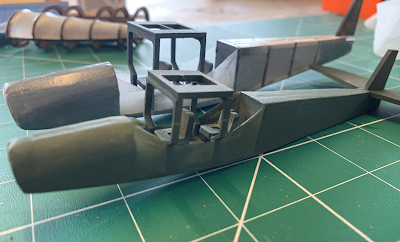
But first a shot of my progress thus far.  Here I've used an Ash veneer to clad the fuselage framework, and balsa blocks for the nose shape.  In these pictures I'm yet to finesse the final shape, but hopefully you get the idea.


I was keen for the interior to closely match the original design, and I'm quite pleased with the outcome. I chose not to paint the sides, to enhance the contrast of the frames when viewed through the little windows.

Another detail which was important to me, was the wing roots.  On the prototype they stop short of the fuselage, their only connection being the wing spars.


Being aware that this little plane might be somewhat fragile, and that I was likely to destroy most of it in the construction process, I have made the upper wing removable.  To achieve this the vertical structural pieces between the wings were made to fit into pockets between two wing ribs.  Upon completion of the wing covering, the hole is cut from the tissue covering material, and these pieces simply slip in, their profile neatly finishing the hole flush with the upper surface of the wing.  

  
The result of these improvement are, I think quite realistic especially so when one remembers the scale of 1:56.  
For these photos I was keen to add some colour and so have blown a quick coat over the upper wing and rear fuselage section.  I'm still to determine the correct colour of the prototype, so for now green it is.
I am really happy with the contrast between the front and rear sections, their construction methods closely reflecting the prototype. 


And finally, rather precariously perched upon its embronic landing gear the aeroplane is being guarded from the marauding children at school by some Empress miniatures, who may or may not get a coat of paint themselves at some point in time.

And so, that is the progress so far.  Sadly not the progress I'd hoped for, however, the rest should be fairly straight forward from here on.

Thank you for visiting the blog.


Saturday 12 October 2019

Vickers Vernon Part 3 - Modifications to the Fuselage Design


By way of an interesting introduction to the post, I include the image below of a Vickers Vimy, the precursor to the Vernon which entered service in October 1918.   It had a 1 ton payload and was capable of striking the heart of Germany, albeit it's arrival was too late to  have any effect upon the outcome of the war.  This was a screen-grab from a video on YouTube and I recommend it to anyone interested in this aircraft.  Note how exposed the crew are!
Once the Vernon is complete, I will modify my kit of parts to make one of these as well.


Image taken from: https://www.youtube.com/watch?v=AJdV5Kof-50, well worth a watch.


Back to the Vickers Vernon model.  
A selection of photographs at http://www.aviadejavu.ru/ have been hugely helpful in refining some of my thinking with this model, which has led to several changes and improvements to the design of the model thus far.  I include this image below, as it confirms my design choices for the central fuselage structure, my model version quite closely resembling that of the prototype.  It's not perfect, and concessions have been made such that the model has sufficient strength to be handled, but even so, I was pleased that my guesstimation wasn't far off.


I had commented in my last post, about the problems I was having covering the rear in tissue.  If only I had seen the following photograph beforehand.  Of particular interest to me are the longitudinal stringers, and the 'fantail' frameworks to the rear frames.  I was also pleased to have confirmed the exact profile of the fuselage as it meets the tail surfaces, and in particular, how the elliptical section transitions into a square section.  These changes will be incorporated into my 3d CAD model.


And so to my real-world model,  I have made some changes to the forward frames, to incorporate spars from which the wing ribs could be fitted.  At this stage, the wing centre-pieces and the fuselage section are married as in the photo above.


I will later add the bracing between the two wing surfaces, and the frameworks which will support the engines.  My design holds the wings at the correct angle and is surprisingly strong.  I learned from photographs that the pilots accessed their cockpit via doors through the 'sad eye' bulkhead I'd mentioned previously, so I scored some panel lines in this area to help give the impression of doors once painted.


In this photo, the top wing is simply sitting upon the fuselage structure.  Once this has been skinned, it will be fitted permanently.  The triangular struts are a little over-scale, another compromise between scale and strength.  I might remake these in wire later.


Please excuse my fat thumb, and the failed rear fuselage mock-up. I couldn't resist offering the pieces together to get a feel for the complete aircraft's dimensions.


And so to the rear section of the aircraft.  I decided that tonight I would test some alternative ideas, which were suggested to me for replicating the stretched canvas skin of the rear fuselage.  However, having already modified the rear frames to take 0.8mm wire stringers, I thought I'd give tissue paper another try. 


The outcome was a bit of a surprise  and better than I'd expected.  
As I'd anticipated trying several methods, I was a bit rough-and-ready when gluing the wire stringers in; after all it was just a test piece and several bent horribly. But even so the effect was very encouraging indeed.  The USB stick gives an impression of the size of the piece.


At the front-end now, and a quick mock-up of how card will be used to replicate the plywood sheathing of the forward fuselage.


 And here are the pieces so far, the card wrapper isn't glued on yet, as I've still to decide upon which style of seats to fit.  The rear section isn't fitted either, but it gives a good idea of how the project is shaping up.  I've decided to create a third fuselage piece for the tail structure mentioned earlier, but that will have wait until next time.


As I write this, I've just finished a very enjoyable day redesigning some aspects of the Schloss Itter project, so my little aircraft projects have taken a back-seat.  Hopefully, now that some significant design elements of the castle and its surroundings are now settled I shall be able to devote some time to finishing these off.

Current aircraft tally: 1 airworthy (+1 P38 Glider!)
                                  6 in build
                                  2 designed but not started.

Until next time, thanks for stopping by, and a special 'Thank you' to the 11 kind folk who have kindly shown support by following my blogging journey.  I plan to continue designing and making things in 1:56, with a focus on things I haven't seen done before.  I hope my jottings will be of interest and I really appreciate the support!  Suggestions for things I can 'makeinminiature' next will be well received.


Best wishes,

James


Tuesday 8 October 2019

Vickers Vernon Part 2 - The Rear Fuselage

The fuselage of the Vickers Venom was, as far as I can determine, built in two pieces.  The front section as detailed in my previous post looks to be of timber construction, with the elliptical framework wrapped in plywood sheet which will no doubt have produced a very strong tubular construction.  However, it's clear from photographs that the rear section must have been a fabric covered as the polygonal framework can be determined by the tapering facets along it's length.


Image result for vickers vernon


My recent experiments with tissue paper covering suggested that this would be quite simple to replicate, subject to constructing a framework with the required shape.  What is in effect required is an icosagonic ellipse.

Thank you Google!


I had expected this to be quite tricky, but as it turned out it was very straightforward.
From my drawings I was able to determine the dimensions of a rectangle which would bound the fuselage at each frame position.  The CAD software has a tool which will construct an ellipse to be a perfect fit within that rectangle.
I could then find the centre of the rectangle and draw radiating lines at 18 degrees from this centre point,  (360/20=18).  


By joining the points where the radiating lines met with the ellipse the Icosagon was created.  It was then a simple matter to delete the construction lines and be left with the correct form.


This process was repeated for each of the frames, and the profiles created were exported into the 3d CAD, extruded by 2mm and assembled to form the rear fuselage construction.


There are still a couple of elements to refine, but I'm happy with the progress to this point.  I think the extra trouble in creating the correct form for the rear of the aircraft will be time well spent.  For the record, I have currently invested about 3 hours in this project which doesn't seem at all bad given it's relatively complex shape when compared with the Storch.


As mentioned, I've been experimenting with tissue paper and shrinking dope as a covering technique, with some success.  Indeed, this may become my go-to solution for finishing MDF models prior to painting as a means of disguising the awkward joints which often become so painfully obvious once painted.
This picture shows the Mk2 Storch at 1:43 scale and it's little 1:56 brother.


It was a natural choice therefore for the rear fuselage element of the Vernon, and I hoped it would pull tight around the icosagonic frames to reveal the longitudinal 'fold' lines.


Sadly, this idea proved less than successful and the tissue paper tended to shrink a little too much causing it to sink between the frames.


My first thoughts as to a solution is to modify the frames to accept thin wires which will run along the corners to provide a structure for the tissue paper to form around.  Whether or not this will be successful we will have to wait and see.  If any blog visitors have a suggestion, please let me know and I'll test some alternatives and report my findings.


These two images give an idea as to my current thinking.


I will leave this post with an interesting photograph of the interior of a troop carrier variant of the Vernon.  The fold-away deck chairs are themselves interesting pieces, and I'll try to incorporate them into the model.


 *** STOP PRESS! *** 

At the point of posting I have just come across some more photographs which confirm much of what I have done, but also suggest some improvements.  So for the sake of providing a fulsome account of the build of this most interesting aircraft, will post this for now and continue the narrative with the corrections next time.  Stay tuned!

Thank you for visiting,

James